
Nitrogen Oxide Treatment System
— Turnkey Nitrogen Oxide (NOx) Treatment System
Product Overview
What nitrogen oxides are, and why they must be treated
NOx is the collective term for nitrogen oxides, dominated by nitric oxide (NO) and nitrogen dioxide (NO2), with trace N2O, N2O3, N2O4 and N2O5. Industrial gas streams are typically 90–95% NO — and NO is only sparingly soluble in water, so it cannot simply be washed out. It must first be reduced to nitrogen gas or oxidised into a water-soluble higher oxide. That single constraint drives every design decision in a deNOx plant.
NOx forms by three routes: thermal NOx (above 1,200–1,300 °C, from the nitrogen and oxygen in combustion air), fuel NOx (from nitrogen bound in the fuel, from about 800 °C), and prompt NOx (flame-front radicals, minor). Identifying which one dominates your process is the first step in route selection.
Uncontrolled NOx causes acid rain, photochemical smog, ground-level ozone and PM2.5, and damages lung function. N2O, formed under poor process control, has a global warming potential roughly 298 times that of CO2. Every major industrial jurisdiction therefore caps NOx — and the limits keep tightening.
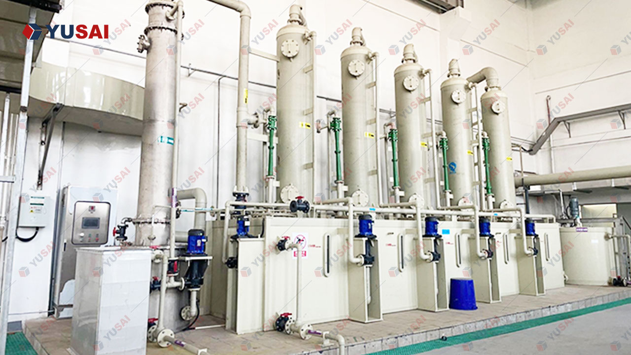
What The Nitrogen Oxide (NOx) Treatment System
The system answers one question: what is the most economical configuration that holds your stack below your legal limit, year after year? A nitric-acid reactor vent at 20,000 ppm and a gas-fired boiler at 200 mg/Nm³ are different problems, so YuSai engineers by route selection first, equipment second.
Four routes, used alone or combined:
- Wet chemical reduction-absorption — NOx is absorbed and reduced to nitrogen in a scrubbing liquid. The route of choice for high-concentration, low-temperature vents, and it removes HCl, Cl2, SO2, HF and ammonia in the same tower.
- SCR (Selective Catalytic Reduction) — reagent injected into a catalyst bed at 250–450 °C. Highest efficiency; the standard choice where ultra-low emission limits apply.
- SNCR (Selective Non-Catalytic Reduction) — the same reduction chemistry without a catalyst, injected into the 850–1,100 °C furnace zone. Lowest capital cost, moderate efficiency.
- Ozone / catalytic oxidation — NO oxidised to highly soluble higher oxides (NO2, N2O5), then removed in a wet or dry scrubber. For low-temperature streams where SCR is impractical.
Where space is tight or limits severe, routes are combined — most commonly SNCR upstream + SCR downstream, where the SCR layer consumes the residual ammonia, cutting reagent consumption while still reaching ultra-low emission.
Applicable feedstock → treatment process → final output
- Feedstock: nitric-acid and aqua-regia reactor off-gas, metal pickling and etching exhaust, nitric acid plant tail gas, and combustion flue gas from boilers, kilns, furnaces, smelters, incinerators and stationary engines.
- Process: particulate knock-out and gas conditioning → temperature adjustment into the active reaction window → reagent metering and injection → reduction across catalyst, in the furnace zone, or in an absorption tower → polishing and demisting → continuous emission monitoring → stack discharge.
- Output: clean stack gas of N2, H2O and CO2 at the applicable emission limit, plus reclaimable by-products where the process allows — regenerated nitric acid, ammonium salt solution and recovered process heat.
Turnkey scope
Single-responsibility delivery: gas sampling and route selection, process design and mass balance, CFD-supported reactor and duct engineering, in-house fabrication of towers, reactors, skids and ducting, reagent and dosing systems, instrumentation and CEMS integration, PLC/DCS programming, export packing, overseas installation, commissioning and operator training. Designed to tie in during a scheduled shutdown and to run unattended in normal operation.
Recovery Value Analysis
1. Compliance value — the avoided cost of non-compliance
In China, the EU and the US, NOx exceedance triggers fines, production restrictions and shutdown orders — an unplanned stoppage costs far more than the deNOx plant itself. The system is specified with a compliance margin rather than to the exact limit, so normal process fluctuation does not create exceedance.
- Reference limits: GB 13271 industrial boilers 30–150 mg/Nm³ (ultra-low emission target ≤50 mg/Nm³), EU IED large combustion plants 100–200 mg/Nm³, US EPA industrial boilers 30–100 ppm with SCAQMD as low as 9–30 ppm, and Germany’s TA-Luft.
- Continuous CEMS reporting turns compliance from an annual stack test into a live operating variable, reducing the risk and cost of regulatory inspection.
2. Material recovery — recovering value from the gas stream
Depending on the route, part of the NOx load and part of the reagent can be returned to the process rather than lost:
- Nitric acid regeneration. In pickling and etching service, hydrogen peroxide scrubbing converts NOx back to nitric acid in situ, cutting make-up acid and neutralisation cost and avoiding the nitrate-laden effluent that caustic scrubbing produces.
- Ammonium salt by-product. Acid gases present in the flue gas (SO2, SO3, HCl) are captured as ammonium sulfate and ammonium chloride, usable as fertiliser or industrial feedstock instead of hazardous waste.
- Recovered process heat. SCR reacts at 250–450 °C, which matches the flue gas temperature between economiser and air preheater in many boiler retrofits, so a correctly placed reactor needs no external reheat.
- Precious-metal aerosol recovery. In refining, the off-gas from aqua regia dissolution and nitric-acid purification reactors entrains fine metal-bearing droplets. A recirculating wet scrubbing circuit concentrates and returns them to the refining process — a secondary recovery point that materially offsets operating cost, and one that is only achievable when the scrubber is designed into the refinery from the start.
- Rinse water reuse. Neutralised demister and blowdown streams are reusable as process rinse water in many circuits.
3. Operating cost reduction
Ammonia consumption is the largest recurring cost in SCR and SNCR service, and catalyst replacement the largest periodic one (typical life 2–5 years). Both are managed by closed-loop NH3/NOx control against live NOx measurement rather than a fixed setpoint, by a staged catalyst arrangement that lets the top layer be replaced without renewing the full charge, by upstream particulate removal and correct reactor placement to slow deactivation, and by reactor geometry engineered for uniform flow and lower induced-draft fan power. Route selection also minimises secondary waste: the hydrogen peroxide and catalytic reduction routes produce no saline wastewater.
4. Comparability across routes
SNCR carries the lowest capital cost but a narrow temperature window; SCR delivers the highest efficiency and the most predictable long-term operating cost at the highest capital cost and largest footprint; wet absorption is the only practical route for very high concentrations at low temperature, at the price of continuous chemical consumption and a wastewater stream; ozone oxidation needs no catalyst and no high temperature but costs more to run.
Because these trade-offs are site-specific, the value analysis is delivered as a written comparison for your plant — capital cost, operating cost per year, reagent consumption, secondary waste volume and achievable outlet concentration for each candidate route — before you commit to a design.
Applicable Materials And Gas Streams
Process off-gas containing nitric acid or aqua regia
These streams are the highest-concentration NOx sources in industry, typically cold, humid and often acidic. They are treated by wet chemical reduction-absorption, usually with oxidation assistance.
- Aqua regia (HCl + HNO3) dissolution reactor off-gas — gold, silver and platinum-group metal (PGM) refining. Very high NOx with HCl and Cl2 present. Typical inlet: several thousand to 20,000 ppm, ambient to 80 °C.
- Nitric acid digestion and purification reactor off-gas — nitric-acid-based leaching, impurity removal and digestion reactors in precious metal and hydrometallurgical refining. Typical inlet: 3,000–30,000 mg/Nm³, ambient temperature.
- Nitric acid plant tail gas — absorber off-gas from nitric acid manufacture. High concentration with residual oxygen; a classic SCR or extended-absorption application.
- Metal pickling, bright dipping, phosphating and desmutting exhaust — stainless steel and alloy surface treatment using nitric acid and nitrate/nitrite salts.
- Nitric-acid etching and electroplating exhaust — PCB etching, semiconductor wet processing, precision metal finishing.
- Nitro-aromatics, explosives, dyes, plastics and intermediate synthesis vent gas — processes using nitric acid, nitrates or nitrites as reagents.
- Precious metal smelting and calcination furnace off-gas — mixed with dust and metal fume, requiring particulate pre-removal.
Combustion flue gas from stationary sources
Large-volume, high-temperature streams where the choice is normally between SNCR, SCR and a hybrid arrangement.
- Industrial boilers — coal, oil, gas and biomass fired; also circulating fluidised bed (CFB) and chain-grate boilers.
- Utility and captive power plant boilers — the classic high-efficiency SCR application, with high-dust and tail-end layouts both available.
- Cement kilns and precalciner kilns — high dust load, high alkali content; a demanding SCR application usually handled by SNCR plus a high-durability catalyst layer.
- Glass furnaces — float, container and speciality glass melting tanks.
- Ceramic, lime and refractory kilns.
- Metallurgical furnaces — sintering and pelletising machines, coke ovens, blast furnace stoves, copper/lead/zinc smelting furnaces, aluminium melting and holding furnaces.
- Waste incineration — municipal solid waste, hazardous waste and medical waste incinerators.
- Stationary engines — diesel and gas engines for power generation, where exhaust temperature is well matched to SCR.
- Refinery process units — fluidised catalytic cracking (FCC) regenerator flue gas and fired heater exhaust.
High-tech and specialty streams
- Semiconductor and display manufacturing waste gas — point-of-use abatement tail gas, where nitrogen used as a purge or carrier gas converts to thermal NOx in the abatement burner, and where nitrogen-bearing precursors (N2O, NF3, NH3) contribute fuel-type NOx.
- Thin-film solar cell and crystalline silicon cell manufacturing exhaust — processes using NF3 chamber cleans and NH3.
- Laboratory and pilot-plant fume hood exhaust — small-volume, high-concentration streams requiring compact packaged units.
Co-contaminants handled in the same system
Because NOx rarely travels alone, the YuSai design treats the following in the same equipment train where the gas composition requires it, avoiding a second scrubbing stage:
- Acid gases: HCl, Cl2, SO2, SO3, HF
- Ammonia (NH3) slip from upstream processes
- Volatile organic compounds (VOC) and odour-causing species
- Fine particulate and metal-bearing fume
- Water vapour and acid mist
Main Equipment
Reagent preparation and supply
- Reductant storage and unloading module — tanks, level instrumentation, transfer pumps and bunded containment for aqueous ammonia (typically 20–25%), urea solution, or liquefied ammonia where the site is licensed for it. Liquefied ammonia carries the lowest operating cost but the strictest safety regime; urea is the safest and most widely accepted where storage permits are a constraint.
- Urea dissolution / pyrolysis unit — for urea-based systems, converts urea solution into ammonia vapour for injection, giving the safety benefit of urea with the injection behaviour of ammonia.
- Metering and distribution skid — mass-flow-controlled dosing pumps and distribution manifolds that split reagent flow proportionally across injection points.
- Chemical dosing package (wet route) — storage, metering and dosing for the scrubbing reagent: sodium hydroxide, hydrogen peroxide, sodium hypochlorite or sulfuric acid, depending on the selected chemistry.
- Oxidant generation package (ozone route) — oxygen feed, ozone generator and injection manifold, with ozone destruction and leak monitoring for safe operation.
Injection and mixing
- Ammonia injection grid (AIG) — multi-zone lance array with individually trimmable nozzles, sized so that reagent distribution matches the measured NOx profile across the duct cross-section rather than assuming a uniform gas.
- Atomising injection lances (SNCR) — air-atomised or steam-atomised lances positioned in the 850–1,100 °C furnace zone, with retractable mounting for maintenance without a full shutdown.
- Static mixer and flow rectifier — a static mixing element plus turning vanes and a flow-straightening grid upstream of the catalyst, ensuring the reagent and NOx are fully mixed and the gas approaches the catalyst face at uniform velocity. This module is the single most important determinant of whether an SCR system reaches ultra-low emission, and it is the part most often under-engineered by low-cost suppliers.
- Compressed air module — instrument air and atomising air supply with dryers, filters and pressure control.
Reaction and absorption
- SCR reactor — vertical or horizontal steel reactor with catalyst support grids, sealing system and access doors, arranged in one to three catalyst layers with provision for an additional future layer. Available in high-dust (upstream of particulate control) or tail-end (downstream, with gas reheat) configuration.
- SCR catalyst — supplied as honeycomb (highest specific surface area, most compact, most widely used), plate-type (best anti-clogging performance in high-dust service) or corrugated (lightest, least wear-resistant) modules. Catalyst formulation is selected per application: V2O5-WO3/TiO2 for the majority of boiler and kiln applications, zeolite-based for high-temperature or alkali-rich gases, and activated carbon or iron-oxide based where the flue gas chemistry demands it.
- Wet absorption tower — multi-stage packed or spray tower with internal recirculation loops, structured or random packing, and a high-efficiency demister. For high-concentration process vents the tower is configured as a counter-current multi-stage absorber to reach high removal rates in a compact footprint.
- Oxidation stage — a dedicated tower stage or inline reactor where NO is oxidised to NO2/N2O5 to render it water-soluble, using hydrogen peroxide, sodium hypochlorite, ozone or non-thermal plasma.
- Alkaline and reductive scrubber stages — downstream absorption stages for the acid gases and residual oxides generated in the oxidation stage.
Gas handling, heat recovery and utility
- Flue gas reheater / heat exchanger — raises tail-end SCR inlet temperature to the catalyst window and recovers heat on the outlet side. Where the plant already has an appropriate temperature zone, the reheater is replaced by correct reactor placement, removing both capital and operating cost.
- Ducting and expansion joints — corrosion-resistant ductwork with expansion joints, dampers and bypass provisions for maintenance without stopping the upstream process.
- Induced draft (ID) fan — sized for the full system pressure drop including a loaded catalyst layer, with variable-frequency drive to match plant load.
- Soot blowing system — steam, compressed-air or acoustic soot blowers arranged to clear particulate from the catalyst face and prevent the ash bridging that silently destroys removal efficiency.
- Particulate pre-removal — cyclone, bag filter or electrostatic precipitator upstream of the catalyst where the gas is dust-laden.
- Mist eliminator and condensate handling — demister, condensate collection and return.
Control, monitoring and safety
- PLC / DCS control system — closed-loop control of reagent dosing against live NOx measurement, with load-following, alarm management, trend logging and remote access.
- CEMS (Continuous Emission Monitoring System) — NOx, O2, temperature and, where required, NH3 slip and flow monitoring at both reactor inlet and stack. The CEMS is the feedback element in the control loop and the evidence base for regulatory reporting.
- Ammonia slip monitoring and interlock — protects against the two consequences of over-injection: reagent waste and ammonium bisulfate (NH4HSO4) formation.
- Safety and gas detection package — ammonia detection, ozone monitoring where applicable, emergency shutdown logic and ventilation interlocks.
Materials of construction
Wetted and gas-contacting surfaces are specified against the actual gas chemistry, not a default:
- PPH (polypropylene homopolymer) with anti-ageing additive — the preferred material for high-concentration acidic process vents, giving long service life in HCl, Cl2 and NOx service with low weight and cost.
- FRP (fibre-reinforced plastic) — for larger towers and ducting in moderately aggressive service.
- 316L and duplex stainless steel — for high-temperature ducting, reactor internals and reagent systems.
- PTFE lining and corrosion-resistant alloy components — for the most aggressive streams and for acidic dew-point conditions in cold-end ductwork.
Process Flow
Route selection — the first step
Before any equipment is specified, the gas stream is characterised and a route is selected. The decision follows a fixed logic:
- High concentration (above roughly 1,000 ppm) + low temperature (below 150 °C) → wet chemical reduction-absorption, with an oxidation stage if the NO:NO2 ratio is unfavourable.
- High concentration + available heat + ultra-low limit → SCR with a reheater, or ozone oxidation followed by wet scrubbing.
- Combustion flue gas at 850–1,100 °C with a moderate limit → SNCR.
- Combustion flue gas at 250–450 °C with a strict limit → SCR.
- Strict limit + limited space, or a large existing boiler → hybrid SNCR + SCR.
Wet chemical route — process flow
- Source capture. Off-gas is captured under negative pressure directly at the reactor, tank or hood, so that no fugitive NOx escapes into the working area. Negative-pressure operation is a safety requirement, not a preference: it guarantees that any leak in the system draws air inward rather than pushing NOx into the plant.
- Particulate knock-out and gas conditioning. A knockout drum, cyclone or packed pre-scrubber removes entrained droplets, dust and metal-bearing aerosol, and quenches the gas to the temperature window demanded by the scrubbing chemistry. In precious metal refining this stage is where entrained metal-bearing material is captured for return to the process.
- Oxidation stage (where required). A controlled dose of oxidant — hydrogen peroxide, sodium hypochlorite, ozone or non-thermal plasma — converts the sparingly soluble NO into NO2 and higher oxides, which are readily soluble. Dosage is set by the measured NO:NO2 ratio at the tower inlet; under-dosing leaves NO unabsorbed, over-dosing wastes chemical and creates excess nitrate in the blowdown.
- Multi-stage counter-current absorption and reduction. The gas rises through successive packed stages while scrubbing liquid is recirculated in counter-current flow. In each stage the oxides are absorbed and chemically reduced, leaving the nitrogen as N2 and the reagent as CO2 and water. Reagent concentration, pH, temperature and liquid-to-gas ratio are controlled per stage.
- Acid gas removal. Stages configured for HCl, Cl2, SO2 and HF removal operate in the same tower, using alkaline or reductive chemistry as appropriate to the species.
- Demisting. A high-efficiency demister removes acid mist and entrained droplets before the gas leaves the tower, protecting the downstream duct, fan and stack from corrosion.
- Recirculation and blowdown management. Scrubbing liquid is recirculated until its dissolved-salt concentration reaches the process limit, then bled off for neutralisation, reuse or by-product recovery. Blowdown rate is the principal operating-cost lever in the wet route.
- Monitoring and discharge. NOx, O2 and temperature are continuously measured; the induced-draft fan discharges the treated gas to the stack. Measured data feeds the control loop and the compliance record.
SCR route — process flow
- Gas source and particulate control. Flue gas leaves the boiler, kiln or furnace. In high-dust configuration the reactor is placed ahead of the particulate collector; in tail-end configuration the gas is cleaned first and the reactor is placed at the stack. The choice governs catalyst pitch, soot-blowing intensity and catalyst life.
- Temperature conditioning. Gas temperature is brought into the catalyst window — 250–450 °C, with 300–400 °C the normal design band — using either correct reactor placement inside the existing thermal profile, or a heat exchanger/reheater with heat recovery.
- Reagent preparation. Aqueous ammonia or urea solution is vaporised and diluted to the injection concentration. Urea systems generate the ammonia in situ by pyrolysis.
- Injection and mixing. Reagent is injected through the multi-zone AIG and thoroughly blended with the flue gas in the static mixer. Mixing quality, not catalyst quantity, is the usual limiting factor on achievable efficiency.
- Catalytic reduction. The mixed gas passes down through the catalyst layers, where NOx is reduced selectively to N2 and H2O. The reaction is selective because the ammonia reacts preferentially with NOx rather than being oxidised by the excess oxygen present — and the presence of that oxygen is itself essential to the reaction.
- Ammonia slip control. The NH3/NOx molar ratio is trimmed continuously against outlet NOx measurement. Ratios that are too low leave NOx unconverted; ratios that are too high waste reagent and cause ammonium bisulfate formation, which is corrosive and fouls air preheater surfaces.
- Dust removal and heat recovery. The treated gas passes through the particulate collector and heat recovery stages, with soot blowers maintaining catalyst cleanliness on a defined cycle.
- Monitoring and discharge. Outlet NOx and NH3 are measured continuously at the stack; data drives the control loop and the compliance record.
SNCR route — process flow
- Injection point selection. Injection lances are positioned in the furnace zone where the gas is at 850–1,100 °C, verified by temperature mapping rather than assumed from the furnace drawing. The correct injection point is the whole of the technology.
- Reagent atomisation. Dilute ammonia or urea solution is atomised into the gas with compressed air or steam, with droplet size controlled so that droplets evaporate and react within the residence window without impinging on tube walls.
- Non-catalytic reduction. Reagent reacts with NOx in the gas phase to form N2 and H2O. No catalyst is used, which removes the catalyst cost but narrows the effective temperature window.
- Residual ammonia management. Where an SNCR stage runs ahead of an SCR stage, the unreacted ammonia is not lost — it is consumed by the downstream catalyst layer. This is the basis of the hybrid route and the reason hybrid systems cut total reagent consumption.
- Monitoring. NOx measured at outlet, with tuning of lance groupings and reagent flow as plant load varies.
Control philosophy
Across all routes the system runs on a single principle: measure, dose, verify, correct — continuously. Rather than setting reagent flow at a fixed value chosen for worst-case conditions, the controller adjusts dosing second by second against live NOx measurement, so the plant uses only the reagent it needs at the load it is actually running. This is what keeps operating cost predictable as plant load and fuel quality vary.
Product Features
Engineering and performance
- Route-agnostic design — the same engineering platform is configured as wet absorption, SCR, SNCR, ozone oxidation or a hybrid, so the recommendation follows your gas stream rather than the supplier’s product catalogue.
- NOx removal from 70% to 95%+, selected to meet ultra-low emission limits (≤50 mg/Nm³) where required.
- Handles the complete NOx family including N2O and NO3, not just NO and NO2.
- Engineered for inlet concentrations from a few hundred ppm up to 20,000 ppm in high-concentration process vent service.
- Ammonia slip controlled below 3 ppm, with interlocked protection against ammonium bisulfate formation and air preheater fouling.
- Multi-zone ammonia injection grid with individually trimable nozzles, matched to the measured cross-sectional NOx profile.
- Static mixer and flow rectifier engineered for uniform velocity at the catalyst face — the decisive factor in reaching ultra-low emission.
- Uniform flow distribution reduces ID fan power and slows catalyst erosion over the plant’s life.
Construction and materials
- PPH with anti-ageing additive, FRP, 316L/duplex stainless and PTFE lining, selected against the actual gas chemistry rather than a default material.
- Compact tower footprint with multi-stage counter-current absorption to achieve high removal in limited floor space.
- Corrosion allowance and dew-point analysis applied to every cold-end surface.
- Modular construction for container transport and rapid site assembly, with flanged sections sized to standard shipping envelopes.
Control and compliance
- Integrated CEMS measuring NOx, O2 and temperature at inlet and stack, with NH3 slip monitoring where required.
- PLC/DCS closed-loop control with load-following, alarm management, historical trending and remote diagnostics.
- Automatic reagent dosing tied to measured NOx, minimising reagent consumption and eliminating manual setpoint drift.
- Compliance-ready data logging structured for regulatory reporting and inspection.
- Fail-safe logic: reagent supply loss, fan trip or CEMS fault triggers a defined safe state rather than an uncontrolled emission.
Integration and operation
- Designed to operate under negative pressure, so fugitive NOx cannot escape into the working area during operation or maintenance.
- Bypass ducting and damper provisions allow maintenance without stopping the upstream reactor, furnace or boiler.
- Retrofittable — the system is routinely engineered into an existing plant envelope and into existing duct runs.
- Delivered as the environmental-control module of a YuSai precious metal refining, e-waste recycling, lithium battery recycling or solar panel recycling line, or as a standalone turnkey plant.
- Multi-contaminant capability: NOx, HCl, Cl2, SO2, SO3, HF, ammonia, VOC and acid mist in a single equipment train where the gas composition allows.
- Bilingual HMI and documentation for export projects, with operating procedures written for the actual installed configuration.
Technical Parameters
The table below gives the design envelope of the YuSai Nitrogen Oxide Treatment System by route. Values are typical design bands used for route shortlisting; final parameters are fixed by project-specific gas testing, mass balance and the emission limit applicable at your site.
| Parameter | Wet absorption | SCR | SNCR | Ozone / catalytic oxidation |
|---|---|---|---|---|
| NOx removal efficiency | 50–99.5% (chemistry and stage count dependent) | 80–95%+ | 30–70% | 60–95% |
| Active temperature window | ambient – 80 °C | 250–450 °C (design band 300–400 °C) | 850–1,100 °C | ambient – 150 °C |
| Catalyst required | No | Yes | No | No (plasma-assisted variants use catalyst) |
| Suitable inlet NOx concentration | low to very high (up to 20,000 ppm) | low to moderate | low to moderate | low to moderate |
| Typical reductant / reagent | NaOH, H2O2, NaClO, H2SO4 | Aqueous ammonia (20–25%), urea solution, liquefied ammonia | Aqueous ammonia, urea solution | Ozone (O3) or non-thermal plasma |
| Ammonia slip | Not applicable | <3 ppm with closed-loop control | Moderate; higher without downstream stage | Not applicable |
| Catalyst type | Not applicable | V2O5-WO3/TiO2, zeolite, iron oxide, activated carbon — honeycomb / plate / corrugated | Not applicable | Optional in plasma-assisted configuration |
| Typical catalyst service life | Not applicable | 2–5 years | Not applicable | Catalyst-dependent |
| SO2/SO3 oxidation | Not applicable | 0.55–1.12% typical, up to ~2% depending on formulation | Not applicable | Not applicable |
| Secondary waste | Saline wastewater (volume chemistry-dependent; avoidable with H2O2 route) | Ammonium salt at low slip; minimal at design conditions | Minor ammonia slip | None in gas phase; ozone safety management required |
| Footprint | Low–medium (tower + reagent area) | Medium–high (reactor + reagent + reheater) | Low (injection system only) | Medium (generator + tower) |
| Capital cost | Low–medium | Highest | Lowest | Medium |
| Best suited to | High-concentration, low-temperature process vents; acid-gas co-treatment | Power, chemical, incineration and refining service with strict limits | Small and medium boilers, kilns and incinerators; retrofits with limited budget or space | Retrofit projects; complex gas composition; low-concentration NOx already served by an existing wet scrubber |
System-level design parameters
- Materials of construction: PPH with anti-ageing additive, FRP, 316L / duplex stainless steel, PTFE lining — selected per gas chemistry and temperature.
- Absorption tower configuration: multi-stage packed or spray tower with internal recirculation loops and high-efficiency demister.
- Reagent storage: aqueous ammonia 20–25%, urea solution, or liquefied ammonia where site licensing permits.
- Instrumentation: NOx, O2, temperature and flow at reactor inlet and stack; NH3 slip and ozone monitoring as applicable.
- Control: PLC or DCS with closed-loop reagent dosing, load following, alarm management and remote diagnostics.
- Monitoring standard: CEMS compliant with the reporting requirements of the applicable jurisdiction.
- Emission targets achievable: GB 13271 industrial boilers 30–150 mg/Nm³ and ultra-low emission ≤50 mg/Nm³; GB 13223 and GB 16297; EU IED BAT-AEL for large combustion plants; US EPA NSPS/NESHAP; Germany TA-Luft.
- Operating mode: continuous, unattended in normal operation, with negative-pressure gas containment.
Reaction chemistry (SCR / SNCR routes)
The primary reduction reactions, including the presence of oxygen, are:
4NO + 4NH3 + O2 → 4N2 + 6H2O
6NO + 4NH3 → 5N2 + 6H2O
2NO2 + 4NH3 + O2 → 3N2 + 6H2O
6NO2 + 8NH3 → 7N2 + 12H2O
NO + NO2 + 2NH3 → 2N2 + 3H2O
Undesirable side reactions, which the control system is designed to suppress:
4NH3 + 3O2 → 2N2 + 6H2O (reagent oxidation — reagent loss)
4NH3 + 5O2 → 4NO + 6H2O (reagent oxidation — NOx formation)
SO3 + 2NH3 + H2O → (NH4)2SO4 (ammonium sulfate — fouling)
SO3 + NH3 + H2O → NH4HSO4 (ammonium bisulfate — corrosive fouling)
The nitrogen leaves the process as molecular nitrogen, which is already the dominant component of the atmosphere. No nitrogen is released as a hazardous compound.
Core Advantages
1. Route selection is engineering-led, not catalogue-led. YuSai builds wet absorption towers, SCR reactors, SNCR injection systems and ozone oxidation packages on the same engineering platform. The recommendation therefore follows the measured gas composition and the emission limit you must meet — not the technology the supplier happens to manufacture. If SNCR plus an optimised scrubber meets your limit, you will not be sold an SCR reactor you do not need.
2. Both ends of the concentration range, in one supplier. Most deNOx suppliers specialise in one end of the market: combustion flue gas (SCR/SNCR specialists) or chemical process vent gas (scrubber specialists). YuSai engineers both, which matters for facilities that have more than one NOx source on site — a refining line with an aqua regia reactor vent at 20,000 ppm and a boiler at a few hundred mg/Nm³ can be handled under a single engineering responsibility.
3. Designed into the process, not bolted on afterwards. The system is engineered alongside the precious metal refining, e-waste recycling, lithium battery recycling and solar panel recycling lines that YuSai supplies. That means the gas capture points, duct routing, negative-pressure containment and reagent storage are designed into the plant layout from the start, rather than retrofitted into residual space with compromised capture and excess duct pressure drop.
4. Precious metal recovery built into the scrubber circuit. For refining applications, the wet scrubbing circuit is configured with a recirculation and recovery loop that concentrates entrained metal-bearing material from the reactor off-gas and returns it to the refining process. This offsets a measurable share of the deNOx plant’s operating cost — and it is achievable only when the scrubber is designed with the refinery rather than bought as a generic gas washer.
5. Corrosion engineering matched to the real gas. High-concentration NOx streams from aqua regia and nitric acid service are aggressively corrosive. YuSai specifies PPH with anti-ageing additive, FRP, 316L/duplex stainless and PTFE lining against the actual gas chemistry and dew point, rather than defaulting to carbon steel with a generic coating that fails in service. Material selection is documented in the design file and traceable to the gas analysis.
6. Mixing and flow engineering that reaches the limit. The static mixer, turning vanes, flow rectifier and multi-zone AIG are engineered and verified for uniform velocity and reagent distribution at the catalyst face. This is the difference between a system that passes its performance test on commissioning day and one that still holds ultra-low emission after three years of load swings and catalyst ageing.
7. Closed-loop reagent control cuts the largest operating cost. Reagent consumption dominates annual operating cost in SCR and SNCR service. Continuous NH3/NOx ratio trimming against live measurement, rather than fixed conservative setpoints, has a direct and measurable effect on annual chemical spend.
8. Compliance margin, not compliance guesswork. Systems are specified with margin above the applicable limit so normal process fluctuation does not create exceedance, and with integrated CEMS data logging structured for regulatory reporting. The operating record is generated by the plant itself.
9. Single-responsibility turnkey delivery. Process design, mass balance, equipment manufacturing, instrumentation, PLC/DCS programming, export packing, overseas installation, commissioning and operator training are delivered by one supplier. There is no interface gap between a reactor vendor, a control vendor and an installation contractor for the customer to manage.
10. Manufacturing and cost position. Equipment is manufactured in Henan, China, in YuSai’s own facility, which means competitive capital cost against European and Japanese deNOx suppliers on comparable specifications, with the same design engineering discipline and full material traceability.
11. Retrofittable and expandable. The system is engineered into existing plant envelopes and duct runs, and reactor designs include provision for an additional catalyst layer so that capacity can be increased if emission limits tighten later — avoiding a second capital project when regulations move.
12. Service model built for export projects. Bilingual documentation and HMI, spare parts availability, remote diagnostic access and on-site support during commissioning and start-up, with defined response commitments set out in Section 10.
Service Process
Pre-sales — specification and design
- Requirement consultation. We review your gas source, process description, applicable emission limit and regulatory jurisdiction, and confirm what the system must achieve.
- Site survey and gas testing. Our engineers attend site (or work from your measured data) to establish gas volume, temperature, NOx concentration and the full composition — O2, moisture, dust, SO2, SO3, HCl, Cl2, HF and VOC. Route selection is based on measured data, not assumptions.
- Route comparison and value analysis. We provide a written comparison of candidate routes covering capital cost, annual operating cost, reagent consumption, secondary waste volume and achievable outlet concentration, so the selection decision is transparent.
- Process design and mass balance. Full process design, heat and mass balance, reactor and duct engineering, and a CFD-supported flow distribution study where the configuration requires it.
- Layout and interface planning. Equipment layout, utility requirements, tie-in points, structural and electrical interfaces, and shutdown scheduling.
- Quotation and contract. Transparent scope of supply, documented exclusions, delivery schedule and payment terms.
In-sales — manufacture and delivery
- Manufacturing. Towers, reactors, skids, ducting and reagent systems fabricated in YuSai’s own facility, with material certificates and welding traceability.
- Quality control. Incoming material inspection, in-process inspection at defined hold points, dimensional and pressure testing, and coating and lining verification.
- Factory acceptance test (FAT). Instrumentation, PLC/DCS logic, control loops and alarm functions are tested before shipment, with the customer or their representative invited to witness.
- Documentation package. Drawings, P&ID, equipment manuals, electrical and instrumentation documentation, operating procedures and maintenance schedules — in bilingual form for export projects.
- Export packing and logistics. Sea-worthy packing sized to container envelopes, shipping documentation, and delivery to site.
- Installation support. Our engineers attend site to supervise installation, align and level equipment, complete duct and utility connections, and verify installation quality against the design.
After-sales — commissioning and operation
- Commissioning. Cold and hot commissioning, control loop tuning, reagent dosing optimisation, load ramp-up and performance testing against the specified outlet concentration.
- Operator training. On-site training for plant operators and maintenance staff covering normal operation, control philosophy, alarm response, reagent handling, routine inspection and troubleshooting.
- On-site support period. Technical specialists remain on site during initial production to support operation until the plant is running stably and the customer’s team is confident.
- Performance verification. Emission testing to confirm the guaranteed outlet concentration, with results documented for regulatory purposes.
- Warranty. Defined warranty period on equipment and workmanship, with defined response commitments for service requests.
- Spare parts. Recommended spares list supplied at handover, with catalyst, packing, demister, pump and instrumentation availability supported long-term.
- Remote diagnostics. Control system remote access for fault diagnosis and performance review, reducing the need for site attendance on routine issues.
- Catalyst and consumable management. Guidance on catalyst activity testing, layer rotation, regeneration and replacement scheduling, so that catalyst change-out is planned rather than reactive.
FAQ
What is a nitrogen oxide treatment system?
It is a plant that removes nitrogen oxides (NOx — principally NO and NO2) from an industrial gas stream before it is discharged to atmosphere. Depending on the gas conditions, it works either by chemically reducing the NOx to harmless nitrogen gas (SCR, SNCR) or by oxidising and absorbing it into a scrubbing liquid (wet chemical absorption, ozone oxidation). YuSai supplies all four routes and combines them where the application requires.
What is the difference between SCR and SNCR?
Both reduce NOx to N2 and H2O using ammonia or urea. SNCR injects the reagent into the hot furnace zone at 850–1,100 °C with no catalyst — lowest capital cost, simpler system, but a narrow temperature window and moderate efficiency (30–70%). SCR passes the gas over a catalyst at 250–450 °C, giving 80–95%+ removal with more predictable long-term performance, at higher capital cost and larger footprint. Because SCR runs at a lower temperature, it needs either a suitable temperature zone in the existing plant or a gas reheater.
Which route is right for my application?
It depends on three numbers: NOx concentration, gas temperature, and the emission limit you must meet. High concentration with low temperature points to wet chemical absorption. Combustion flue gas with a strict limit points to SCR. Flue gas with a moderate limit and limited space points to SNCR or a hybrid. Send us your gas analysis and we will give you a written route comparison with cost figures for each option.
Can the system handle very high NOx concentrations, such as the off-gas from an aqua regia dissolution reactor?
Yes. Wet chemical reduction-absorption is specifically suited to this duty, and YuSai systems are engineered for process vents in the 20,000 ppm range, reducing them to below the applicable discharge limit. The system simultaneously removes HCl, Cl2 and SO2, which are normally present in aqua regia off-gas, in the same equipment train.
What reductant does the system use, and which is best?
Aqueous ammonia (20–25%), urea solution, or liquefied ammonia. Liquefied ammonia has the lowest operating cost but is subject to the strictest storage and handling regulation. Urea solution is the safest and easiest to permit, at slightly higher reagent cost. Aqueous ammonia sits between the two and is the most common choice. YuSai specifies the option that fits your site’s licensing and storage constraints.
What removal efficiency can be guaranteed?
Wet absorption, SCR and ozone oxidation routes reach 95%+ and can be engineered to meet ultra-low emission limits of ≤50 mg/Nm³. SNCR alone typically achieves 30–70%. Where SNCR alone cannot reach your limit, a hybrid SNCR plus SCR arrangement is used — the SNCR stage does the bulk reduction and the SCR layer consumes the residual ammonia, reaching ultra-low emission at lower total reagent consumption than SCR alone.
What is ammonia slip, and how is it controlled?
Ammonia slip is unreacted ammonia leaving the reactor. It matters because excess ammonia reacts with SO3 to form ammonium bisulfate (NH4HSO4), which is corrosive and fouls air preheater and duct surfaces, and because it is wasted reagent. YuSai controls slip to below 3 ppm using closed-loop NH3/NOx ratio control against continuous outlet NOx measurement, with interlocked protection against over-injection.
Does the system produce secondary waste?
It depends on the route. Wet scrubbing with sodium hydroxide or sodium hypochlorite produces a saline wastewater stream that must be treated or evaporated. The hydrogen peroxide route does not, and it regenerates nitric acid in situ in pickling and etching service. SCR and SNCR routes convert the nitrogen to N2 and produce no routine waste stream, though acid gases present in the flue gas are captured as ammonium salts. Secondary waste volume is quantified explicitly in the route comparison so you can weigh it against capital and operating cost.
Which emission standards can the system meet?
The system is engineered to GB 13271 (China, industrial boilers, 30–150 mg/Nm³, with ultra-low emission target ≤50 mg/Nm³), GB 13223 and GB 16297, EU Industrial Emissions Directive BAT-AEL for large combustion plants (typically 100–200 mg/Nm³ for existing large plants), US EPA standards under the Clean Air Act including NSPS and NESHAP (industrial boilers typically 30–100 ppm, with SCAQMD limits as low as 9–30 ppm), and Germany’s TA-Luft. Confirm your jurisdiction and limit at enquiry stage and the design will be targeted to it.
Can the system be retrofitted to an existing boiler, kiln or reactor?
Yes. Retrofit is a routine scope. The two critical constraints are available space and available flue gas temperature. Where the existing thermal profile includes a 250–450 °C zone, an SCR reactor can often be placed without a reheater, removing both capital and operating cost. Where space is tight or the temperature is unsuitable, SNCR, ozone oxidation or a hybrid arrangement is used instead.
How long does delivery and installation take?
Lead time depends on route and scope, and is confirmed at contract stage. The design intent is that installation and tie-in are completed during a scheduled plant shutdown, with the system supplied in modular form sized to container transport to minimise site assembly time. Commissioning and performance testing follow immediately after installation.
What is the operating and maintenance burden?
The system runs continuously and unattended in normal operation. Routine work is limited to reagent replenishment, periodic inspection of injection lances and nozzles, soot blowing cycles where applicable, scrubber liquid chemistry control in the wet route, and catalyst activity monitoring in the SCR route. Catalyst replacement is the main periodic cost item, with typical service life of 2–5 years. Remote diagnostics allow most control-related issues to be resolved without a site visit.
Can one system handle NOx and other pollutants at the same time?
Yes. In wet-route applications the same tower handles NOx together with HCl, Cl2, SO2, SO3, HF, ammonia and acid mist. In SCR and SNCR applications, acid gases in the flue gas are captured as ammonium salts. Combining duties in one equipment train reduces both capital cost and footprint compared with separate abatement stages.
Do you provide installation, commissioning and training?
Yes — full turnkey delivery. YuSai supplies process design, equipment manufacturing, export packing, overseas installation supervision, cold and hot commissioning, performance testing against the guaranteed outlet concentration, operator and maintenance training, and a defined on-site support period during initial production. Bilingual documentation and HMI are provided for export projects.
How do I get a quotation?
Send us the following and we will revert with a route recommendation and budget quotation: gas source and process description, measured or estimated gas volume, gas temperature, inlet NOx concentration, full gas composition where available (O2, moisture, dust, SO2, HCl, Cl2, VOC), and the emission limit and jurisdiction that applies. If you do not have a full gas analysis, we will advise what to measure.
Standards and Sources Referenced
Regulatory limits, technology performance bands and reaction chemistry quoted on this page are drawn from the following public sources:
- Condorchem Envitech — Removal of NOx (nitrogen oxides); NOx abatement systems (SCR/SNCR temperature windows, catalyst types, reducing agents, absorption chemistry)
- DAS Environmental Expert — Eliminating NOx in the semiconductor industry (NOx formation mechanisms, thermal/fuel/prompt NOx thresholds, N2O global warming potential, TSUGA and ALCEA treatment routes)
- Linde Gas — NOx abatement with LOTOX (ozone low-temperature oxidation, >95% removal, N2O5 formation and scrubber removal)
- USP Technologies — Nitrogen Oxides Abatement (EPA nitric acid plant standards, hydrogen peroxide scrubbing chemistry, nitric acid regeneration)
- Babcock & Wilcox — Nitrogen Oxides (NOx) Primer (thermal and fuel NOx mechanisms, 90–95% NO in flue gas, SCR ≥90% reduction, combustion-side control measures)
- Sumitomo Heavy Industries — Flue Gas Denitrification Systems (high-dust versus tail-end SCR, catalyst selection, hybrid SNCR+SCR cost reduction)
- Yara — NOx Control Systems (SNCR up to 80%, SCR up to 95%, hybrid SNCR/SCR for space-constrained sites)
- Catalytic Products International — NOx abatement case studies (SCR for calciner NOx/CO control, ammonia abatement)
- Scrubber performance figures for high-concentration process vent service are benchmarked against published Chinese deNOx equipment practice for nitric-acid reactor off-gas (20,000 ppm inlet, >30,000 mg/Nm³, PPH negative-pressure absorption towers, 99.5% absorption efficiency).
- Emission limit ranges are as published for GB 13271, GB 13223, GB 16297, EU Industrial Emissions Directive BAT-AEL for large combustion plants, US EPA Clean Air Act NSPS/NESHAP, SCAQMD rules and Germany’s TA-Luft. Always confirm the specific limit applicable to your installation with your local environmental authority.
Request a Route Recommendation
Send us your gas conditions and we will provide a written comparison of candidate treatment routes with capital cost, annual operating cost, reagent consumption, secondary waste volume and achievable outlet concentration.
Please include: gas source and process description · gas volume · gas temperature · inlet NOx concentration · gas composition (O2, moisture, dust, SO2, HCl, Cl2, VOC) · applicable emission limit and jurisdiction.
Henan YuSai Precision Machinery Co., Ltd. (YuSai Machinery) Precious metal refining · e-waste recycling · lithium battery recycling · solar panel recycling · air pollution control
Nitrogen Oxide Treatment System — engineered to your gas, guaranteed to your limit.

Get A Free Quote
Fill in the form below and our service team will get back to you within 24 hours with a recommended process flow and quotation.
- +86 18339216321
- info@yusaipreciousmetals.com
- Zhengzhou.Henan.China
If you be interested in our equipment and solutions, please to contact us.
- +86 18339216321
- info@yusaipreciousmetals.com
- zhengzhou.henan.china