
Copper Electrolysis Plant
— Turnkey Copper Electrolysis Plant
Copper Electrolysis Plant by YuSai Machinery is a turnkey electrorefining line that upgrades copper anodes and copper-bearing secondary materials into 99.99% high-purity cathode copper, with cathode chemistry engineered to Cu-CATH-1 (BS EN 1978) — the chemistry basis of LME Grade A copper.
The plant integrates anode preparation, an acid-proof modular cellhouse with 316L stainless steel permanent cathodes, IGBT rectifier power, electrolyte circulation and purification, cathode stripping and washing, cell-level short-circuit monitoring, and closed-loop acid mist and NOx abatement. Gold, silver, platinum, palladium, selenium and tellurium are concentrated into anode slime and recovered as a separate high-value stream instead of being lost in the copper.
Product Overview
A copper electrolysis plant — also called a copper electrorefining plant, electrolytic copper refining plant or copper cathode production line — is an industrial facility that purifies copper electrochemically. Impure copper anodes are suspended in an acidic copper sulfate electrolyte, and a low-voltage direct current is passed between anode and cathode. Copper dissolves from the anode as Cu²⁺ ions, migrates through the electrolyte and is reduced back to metallic copper on the cathode, building up a dense, high-purity deposit. Metals more noble than copper — gold, silver, platinum, palladium, selenium and tellurium — do not dissolve and settle to the cell bottom as anode slime, while base impurities such as nickel, arsenic, antimony, bismuth, iron and zinc are held in solution or precipitated and removed by electrolyte purification. It is the only commercially proven route to 99.99% copper at industrial scale: chemical and pyrometallurgical methods cannot remove the last few hundred parts per million of impurity, whereas electrolysis can, because copper’s deposition potential is more favourable than that of the metals it leaves behind.
In short, the plant takes copper anodes cast from blister copper, anode copper or smelted secondary copper — normally 98–99% copper — and returns 99.99% cathode copper with chemistry engineered to Cu-CATH-1 / BS EN 1978, the chemistry basis of LME Grade A, with 99.995% and 99.999% available on a two-stage refining configuration. The anodes are straightened, lugged and bagged, then loaded into a cellhouse of acid-proof electrolytic cells, where an IGBT rectifier drives dissolution at the anode and deposition at the 316L stainless steel cathode. The electrolyte is continuously circulated, held at 58–65 °C and purified to keep nickel, arsenic, antimony and bismuth below their interference thresholds; cathodes are stripped, washed and bundled on a set cycle; anode remnants return to the melting furnace. Alongside the cathode, the line produces an anode slime concentrate, a nickel-bearing electrolyte by-product, and a closed loop of recycled electrolyte and anode scrap.
Electrorefining and electrowinning are not the same process, and the distinction decides which plant a site actually needs. Electrorefining (ER) starts from a solid metallic anode — cast copper anode plates — and uses the anode itself as the copper source, which is the standard route for smelted and secondary copper. Electrowinning (EW) starts from a solution and uses an insoluble anode, which is the route for copper recovered from leach liquors, spent electrolyte, PCB etching waste and low-grade copper-bearing water. YuSai builds both configurations and, where a site handles solid anodes and copper-bearing solutions together, supplies a hybrid layout in which an electrowinning module runs alongside the electrorefining cellhouse and shares the rectifier room, busbar and electrolyte purification circuit.
Overall, a copper electrolysis plant is not a catalogue item but a mass-balance and electrical-balance problem: anode assay, slime behaviour, silver and bismuth content, target current density and the impurity load arriving in the electrolyte all move together, and a plant designed for one feedstock runs badly on another. YuSai therefore engineers each line upward from the incoming material — anode specification first from your assay, then current density and electrode spacing matched to slime settling behaviour, then electrolyte purification sized for the impurity accumulation rate, with the rectifier, busbar and cellhouse configured around that electrical duty. The result is cathode quality that holds across long campaigns instead of drifting out of specification after the first few anode cycles.
These plants sit at the refining end of the copper chain. They serve copper smelters upgrading blister copper to marketable cathode; secondary copper recyclers converting smelted scrap into reference-grade metal; e-waste and PCB recycling operations that need a route from mixed copper-bearing fractions to a sellable premium product; precious-metal refineries using copper as a collector metal for gold, silver and PGMs; and copper wire and rod producers who want to control their own cathode supply. In every case the plant converts a discounted intermediate into metal that trades against the reference market price.
Recovery Value Analysis
The Value Streams a Copper Electrolysis Plant Creates
1. Cathode copper — the primary revenue stream. Refined cathode is priced against the LME Grade A cash settlement rather than against a scrap or concentrate discount, and that changes the economics more than any throughput increase can. Moving from a 98–99% copper intermediate to 99.99% cathode typically unlocks three separate margin improvements at once: a grade uplift from the impurity removal itself, a much higher payability on the copper content, and the removal of treatment and refining charge deductions that apply to unrefined copper material. Crucially, it also removes the discount applied for out-of-specification chemistry — arsenic, antimony and bismuth penalties can quietly consume a large share of the gross margin on secondary copper.
2. Anode slime — usually the second-largest revenue line. Gold, silver, platinum, palladium, selenium and tellurium are insoluble in the electrolyte and report to the cell bottom as anode slime, typically at 0.2–1.0% of the anode mass. That number looks small until it is priced: on a typical smelter anode the contained gold and silver value alone can reach several percent of the copper value, and on e-waste-derived or high-silver feedstock the slime stream can rival or exceed the copper margin. A plant that is designed with proper slime collection, bagging and dewatering turns a waste-handling problem into a traded concentrate.
3. Electrolyte purification by-products. Copper and nickel build up in the circulating electrolyte as the campaign proceeds. Instead of being bled to effluent, they are recovered — copper by cyclone electrowinning or an electrowinning cell, nickel as nickel sulfate or nickel carbonate through membrane separation, solvent extraction with P204, P507 or C272, and evaporation-crystallisation. The purified acid returns to the cellhouse.
4. Anode scrap. Between 12% and 20% of each anode’s weight remains as undissolved scrap. It is washed, packed and returned straight to the melting furnace, so the copper is recycled internally rather than purchased again.
5. Reduced disposal and compliance cost. A closed electrolyte loop, hooded cells and a scrubbed off-gas system eliminate the spent-acid bleed and acid mist discharge that dominate the operating cost of an uncontrolled refinery. What would otherwise be a regulated waste stream becomes a recoverable product stream.
Typical Recovery Performance
Copper recovery from anode to cathode exceeds 99%, gold and silver recovery into anode slime and downstream precious-metal refining exceeds 99%, and the overall metal recovery of a YuSai copper electrolysis line reaches 95%+ across the full flowsheet. Cathode purity is 99.99% Cu as standard, with 99.995% and 99.999% available on a two-stage refining configuration. Silver refined from the slime stream downstream reaches 99.99% purity.
How the Value Is Realised
The economics of a copper electrolysis plant are decided before the first cell is energised, and they are decided by the feedstock. Silver and bismuth content set the slime revenue and the electrolyte purification duty. Anode thickness sets the scrap rate and the remelt load. Impurity levels set the current density the plant can sustain without losing cathode quality. This is why YuSai tests every customer’s incoming material free of charge before quoting: the same plant specification can produce a very different return on two different anodes, and the flowsheet should be built around the assay rather than the assay fitted to a fixed design.
The practical consequence for buyers is simple — send a representative anode sample and a target cathode specification, and the payback case can be modelled on real metal rather than on a spreadsheet assumption.
Applicable Materials
Group A — Primary Copper Anodes
Suitable feedstock: blister copper and anode copper cast from smelting, typically assaying 98–99% copper, supplied as anode plates with cast lugs. This is the classic electrorefining feedstock and the configuration for which current density, electrode spacing and slime behaviour are best understood. Higher anode assay — 99% and above — reduces the electrolyte purification load and permits operation towards the upper end of the current-density range, which is why anode assay is the first parameter YuSai fixes with a customer.
Processing: anode straightening and lug trimming → anode bagging → electrolytic refining in a CuSO₄–H₂SO₄ electrolyte → periodic cathode stripping → slime collection and dewatering.
Finished product: 99.99% cathode copper engineered to Cu-CATH-1 chemistry, plus anode slime concentrate and internally recycled anode scrap.
Group B — Secondary and Recycled Copper
Suitable feedstock: copper anodes cast from smelted secondary copper such as copper alloy particles, mixed metal powder from cable and PCB processing, copper granules, copper shavings and machining swarf after melting and casting, and crude copper recovered from e-waste smelting.
Processing: melting and anode casting → pre-treatment to remove tin, lead, iron and aluminium where present → reduction to remove free oxygen → anode casting → electrolytic refining with electrolyte purification sized for the higher impurity load that secondary anodes carry.
Finished product: the same 99.99% cathode copper specification as the primary route. Secondary anodes are the single most common feedstock for YuSai plants, because the premium uplift from discounted secondary copper to market-reference cathode is largest here.
Group C — Copper-Bearing Residues and By-Products
Suitable feedstock: copper fractions from printed circuit board and WEEE processing, copper-containing smelting residues, copper oxide and copper sulfide concentrates on the leaching route, copper cement and black copper recovered from cyclone electrowinning.
Processing: leaching and filtration → solvent extraction → electrowinning in a CuSO₄–H₂SO₄ electrolyte using insoluble anodes, or melting and casting into anodes for the electrorefining route where the material is metallic and thick enough to cast.
Finished product: 99.99% cathode copper, with the accompanying gold, silver and PGM values recovered downstream through the anode slime or precious-metal refining circuit.
Group D — Copper-Bearing Solutions
Suitable feedstock: spent copper electrolyte, acid etching waste liquid and micro-etching waste liquid from PCB manufacturing, copper sulfate and copper chloride process solutions, and copper-loaded leach or solvent-extraction liquors.
Processing: pre-treatment to remove organics and suspended solids → optional membrane separation → electrowinning at controlled current density, with the depleted solution returned to the process or advanced to nickel recovery.
Finished product: high-purity cathode copper plus regenerated etchant or recycled acid, which allows a PCB plant to close its own copper loop instead of paying for waste-liquid disposal.
Group E — Copper Powder and Cemented Copper
Suitable feedstock: fine copper powder, cemented copper, copper sludge and filter-press copper cake.
Processing: briquetting or melting and anode casting where the material can be agglomerated, or leaching and electrowinning where it cannot, followed by standard refining.
Finished product: 99.99% cathode copper; the material can also be routed to electrolytic copper powder production where fine powder is the target product.
Pre-Treatment Requirements
Materials containing significant tin, lead, solder or aluminium require pre-treatment before electrolysis, because these elements form compounds that contaminate the electrolyte and degrade cathode quality. Oil, grease, plastics and organic residue must be removed before melting to avoid anode porosity and carbon contamination. Highly oxidised material requires a reduction step to remove free oxygen before anode casting. Feedstock that is too thin or too friable to cast into a stable anode plate is routed to the leaching and electrowinning path instead.
Main Equipment
A YuSai copper electrolysis plant is supplied as an integrated line of sub-systems. Each is engineered as a module so the plant can be shipped, installed and expanded without rebuilding the cellhouse.
1. Anode preparation and casting unit. Melting furnace, anode casting mould or casting wheel, lug trimming and straightening station, and anode weighing. Produces dimensionally uniform anodes — the single most important precondition for even current distribution across the cell.
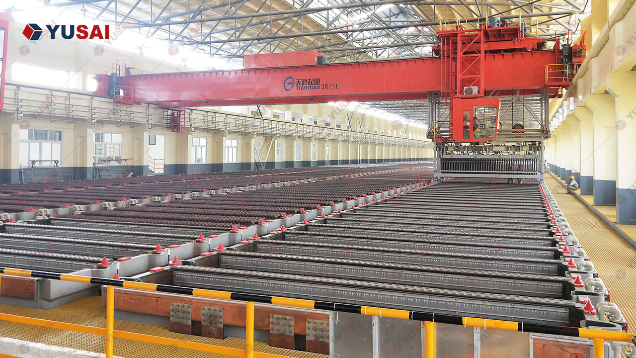
2. Electrolytic cellhouse. Acid-proof electrolytic cells in FRP, PP or concrete with a corrosion barrier, electrode spacing and alignment fixtures, copper busbar and cell insulation, and hooded cell covers with acid mist collection tappings. Modular layout allows staged expansion by adding cell banks rather than rebuilding.
3. Electrodes. Lead-calcium-tin or lead-antimony alloy anodes for the electrorefining circuit, and 316L stainless steel permanent cathode plates with insulating edge strips for the cathode circuit. Permanent cathodes are used rather than starter sheets because they eliminate the starter-sheet production step, give consistent plate geometry, and carry a service life measured in years rather than days.
4. Power supply and busbar. IGBT high-frequency switching rectifier with 12-pulse or 24-pulse configuration, DC busbar, current and voltage regulation, and an optional polarity-reversal pulse mode. The rectifier is isolated from the acid-gas environment of the cellhouse, which is the main reason YuSai specifies IGBT units in a separate electrical room rather than thyristor sets inside the cell hall.
5. Electrolyte circulation system. Circulation pumps, heat exchangers or immersion heaters, filtration units, head tanks, flow measurement and per-cell flow control. Circulation rate and temperature stability decide whether the cathode deposit grows dense and smooth or nodular and impure.
6. Electrolyte purification and decopperising system. Membrane separation to split diluted acid from the nickel-bearing solution, cyclone electrowinning or an electrowinning cell for copper removal, optional solvent extraction with P204, P507 or C272 for nickel and impurity separation, and a nickel sulfate evaporation and crystallisation unit. Purified acid is returned to the cellhouse.
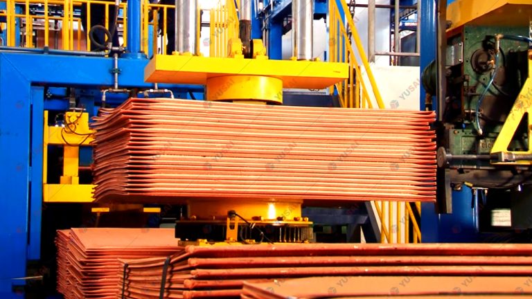
7. Cathode handling system. Cellhouse crane, cathode stripping machine, cathode washing station, and cathode shearing or bundling and strapping equipment for dispatch-ready cathode bundles.
8. Anode scrap handling system. Anode scrap washing, polishing and packing station, with the washed scrap returned to the melting furnace.
9. Anode slime collection and dewatering system. Slime pump, filter press, slime drying and packaging. Designed for low-loss transfer because slime is the highest-value stream per tonne in the plant.
10. Instrumentation and process control. PLC with touch-screen HMI, per-cell voltage monitoring, electrolyte and busbar temperature monitoring, current-density control, short-circuit detection and alarm, and full parameter logging with historical query. Safety interlocks trip the rectifier automatically when current, voltage or temperature moves outside the operating window — a feature that prevents an off-specification cathode campaign rather than merely reporting it afterwards.
11. Utilities and environmental control. Hooded cells with closed acid mist collection and alkaline scrubbing, ozone tail-gas absorption, NOx treatment where nitrate-bearing solutions are processed, wastewater neutralisation and reuse, and demineralised water supply.
Working Process
The Working Principle in One Paragraph
When direct current is applied across an anode–cathode pair in a CuSO₄–H₂SO₄ electrolyte, copper at the anode loses electrons and dissolves into solution as Cu²⁺. Those ions migrate through the electrolyte under the electric field and are reduced back to metallic copper at the cathode surface. Because copper’s deposition potential is more favourable than that of the impurity metals present, only copper — and traces of the most reactive impurities, which are controlled by electrolyte purification — deposits on the cathode. Noble impurities such as gold, silver, platinum and palladium never dissolve at all, and settle as anode slime.
Step-by-Step Workflow
Step 1 — Incoming material assay and flowsheet lock-in. A representative sample of the customer’s anode or copper-bearing material is assayed for copper, precious metals and the full impurity suite. The anode specification, target current density and electrolyte purification duty are fixed from that assay. No equipment is specified before this step.
Step 2 — Anode preparation. Cast anodes are straightened, lugs are trimmed to a uniform contact geometry, and each anode is weighed. Anodes are wrapped in anode bags, which retain slime and prevent it from drifting onto the cathode.
Step 3 — Cell loading. Anodes and cathodes are loaded into the electrolytic cells in an alternating arrangement, with one cathode between each anode pair. Electrode spacing is set by alignment fixtures so that current distribution is even across the full plate area.
Step 4 — Electrolyte preparation and circulation. The electrolyte is made up to the specified copper and free-acid concentration, heated to operating temperature and circulated through the cellhouse. Level control and per-cell flow control maintain identical hydraulic conditions in every cell.
Step 5 — Electrolysis. The IGBT rectifier applies controlled DC current to the electrodes. Copper dissolves from the anode and deposits on the cathode. Dissolved impurities accumulate in the electrolyte; insoluble impurities settle into the anode bags as slime.
Step 6 — Electrolyte purification. A side stream is continuously drawn from the circulating electrolyte and processed to remove accumulated nickel, arsenic, antimony and bismuth. Copper is recovered by cyclone electrowinning, nickel as nickel sulfate or nickel carbonate, and the purified acid is returned to the cellhouse. This is what keeps cathode quality constant over long campaigns.
Step 7 — Cathode stripping. Once the deposit reaches the target thickness, the cathode is lifted, stripped from the stainless steel plate, and the plate is cleaned and returned directly to the cell. Stripping cycles are scheduled to hold deposit quality rather than to maximise plate weight.
Step 8 — Cathode washing and finishing. Stripped cathodes are washed to remove entrained electrolyte and copper sulfate, then sheared or bundled and strapped for dispatch. Residual copper sulfate on the plate surface is a rejection point in most cathode specifications, so washing is a specification step, not a housekeeping step.
Step 9 — Anode scrap return. Partially dissolved anodes are withdrawn, washed to remove adhering slime, and returned to the melting furnace for re-casting.
Step 10 — Slime collection and dewatering. Anode slime is washed out of the bags, pumped to a filter press, dewatered, dried and packed as a concentrate for precious-metal recovery.
Step 11 — Off-gas and wastewater control. Acid mist from the cells is captured at the hood, scrubbed, and any residual ozone or NOx treated before discharge. Wastewater from washing and electrolyte handling is neutralised, and process water is recovered for reuse.
Copper Electrolysis Plant Process Flow

Process Flow of a YuSai Copper Electrolysis Plant. The centre spine runs from the incoming copper anode through assay lock-in, anode preparation and the electrolytic cellhouse to 99.99% cathode copper. Two side streams leave the cellhouse: anode slime is drawn off to the left for filter-pressing, drying and precious-metal recovery, and electrolyte purification is drawn off to the right for copper and nickel by-product recovery and acid return. Anode scrap loops back through the melting furnace into anode preparation, and acid mist is hooded, scrubbed and discharged compliantly.
Product Features
Complete published process parameters. The full operating window — current density, cell voltage, current efficiency, electrolyte composition and temperature, electrode spacing, stripping cycle, anode scrap rate, slime generation and DC energy consumption — is published in the technical parameters table below, not withheld. Buyers can check the design against their own metallurgical assumptions before an enquiry.
Engineered to a named product standard. Cathode chemistry is engineered to Cu-CATH-1 to BS EN 1978, the chemistry basis accepted by the LME for Grade A copper, rather than to an in-house “99.9% pure” claim.
Free incoming-material testing. The flowsheet is built on a real assay of the customer’s own material. This is provided free of charge and is the basis of every YuSai quotation.
Both process routes in one supply scope. Electrorefining for solid cast anodes and electrowinning for copper-bearing solutions, supplied separately or as a hybrid layout sharing one rectifier room and electrolyte circuit.
Designed around the slime, not just the copper. Slime collection, bagging, transfer and dewatering are engineered for low-loss handling and sized on the assayed precious-metal content, because on many feedstocks the slime is the second-largest revenue line.
Permanent 316L stainless steel cathodes. Consistent plate geometry, no starter-sheet production step, and a service life measured in years. Plates are cleaned and returned to the cell immediately after stripping.
IGBT rectifier with parameter interlock. High-frequency switching rectifier with polarity-reversal pulse option, isolated from the acid-gas environment. The control system trips the rectifier automatically on abnormal current, voltage or busbar temperature, so a drifting campaign is stopped rather than discovered in the assay report.
Continuous electrolyte purification. Membrane separation plus cyclone electrowinning removes accumulated nickel, arsenic, antimony and bismuth and returns purified acid to the cellhouse. This is what holds cathode quality flat across a long campaign.
Closed acid mist and off-gas control. Hooded cells with closed collection, alkaline scrubbing, ozone tail-gas absorption and NOx treatment where required — with no secondary pollution stream.
Modular, expandable cellhouse. Cell banks, busbar and rectifier capacity are configured so that capacity can be added in stages. Plants are shop-preassembled to shorten site works.
Turnkey delivery. Process design, engineering, manufacture, factory performance testing with the customer’s own material, shipping, installation, commissioning, performance verification and operator training are supplied as one scope.
Honest specification boundary. The plant produces cathode whose chemistry meets the Cu-CATH-1 specification. LME deliverability separately requires the producer brand to be on the LME registered list — YuSai states this distinction explicitly rather than implying that a compliant assay automatically equals LME-registered metal.
Technical Parameters
The table below lists the design and operating parameters of a YuSai copper electrolysis plant. Values are the engineering design window for copper electrorefining; the final configuration is fixed after incoming-material testing, because anode assay, slime behaviour and impurity load move these values within the stated range.
| Parameter | Specification / operating range | Engineering notes |
|---|---|---|
| Process route | Copper electrorefining (ER); optional electrowinning (EW) or hybrid ER + EW layout | ER for solid cast anodes, EW for copper-bearing solutions |
| Feed anode copper content | ≥ 98% Cu (blister copper); ≥ 99% Cu preferred | Lower anode assay increases electrolyte purification duty |
| Product purity | Cu ≥ 99.99% (4N) standard; 99.995%–99.999% optional | 5N requires two-stage refining |
| Product grade basis | Cu-CATH-1 to BS EN 1978; LME Grade A chemistry basis | LME deliverability additionally requires approved-brand registration |
| Controlled impurity elements | Ag, As, Sb, Bi, Pb, Ni, Fe, S, Se, Te, O | Individually limited and reported on the Certificate of Analysis |
| Total controlled impurity content | ≤ 65 ppm | Cu-CATH-1 basis |
| Current density | 220–320 A/m² design window; up to 350 A/m² in high-rate mode | Set from anode quality and slime settling behaviour |
| Cell voltage | 0.25–0.35 V per cell | Excludes busbar and contact losses |
| Current efficiency | 92–97% | Declines with short-circuit rate and impurity build-up |
| Electrolyte composition | Cu 40–50 g/L; free H₂SO₄ 150–200 g/L | Adjusted to feed assay and anode dissolution rate |
| Electrolyte temperature | 58–65 °C | Maintained by heat exchanger or immersion heater |
| Electrode spacing | 95–110 mm centre-to-centre | Set by alignment fixture; affects cell voltage |
| Cathode stripping cycle | 7–14 days between strippings | Scheduled to hold deposit quality |
| Anode service life | 21–28 days per anode | Depends on anode thickness and current density |
| Anode scrap rate | 12–20% of anode weight | Washed and returned to the melting furnace |
| Anode slime generation | 0.2–1.0% of anode weight | Higher in secondary and high-silver feedstock |
| DC energy consumption | 180–250 kWh per tonne of cathode copper | Function of current density and current efficiency |
| Electrolyte circulation | 15–25 L/min per cell | Per-cell flow control for uniform conditions |
| Electrolyte purification | Membrane separation + cyclone electrowinning; optional P204 / P507 / C272 solvent extraction | Removes Ni, As, Sb, Bi; purified acid returned to cellhouse |
| Nickel by-product route | Nickel sulfate / nickel carbonate via extraction, evaporation and crystallisation | Converts an electrolyte bleed into a saleable product |
| Cathode plate | 316L stainless steel permanent cathode, 3–4 mm, insulated edge strips | Service life measured in years |
| Anode plate | Pb-Ca-Sn or Pb-Sb alloy | Corrosion-tolerant in H₂SO₄ electrolyte |
| Cell body | FRP / PP / acid-proof concrete with corrosion barrier | Modular cell banks for staged expansion |
| Anode bag | Slime-retaining filter fabric, replaceable | Retains slime at the anode, protects cathode quality |
| Rectifier | IGBT high-frequency switching rectifier, 12-pulse or 24-pulse; optional polarity-reversal pulse | Installed in a separate electrical room, isolated from acid gas |
| Busbar | Copper busbar with cell insulation and contact monitoring | Contact losses are a primary current-efficiency loss point |
| Process control | PLC + touch-screen HMI; logging of current, voltage, temperature and electrolyte parameters | Historical query for troubleshooting campaigns |
| Interlocks | Automatic rectifier trip on abnormal current, voltage or busbar temperature | Prevents an off-specification campaign rather than reporting it |
| Short-circuit management | Per-cell voltage monitoring with alarm | Directly protects current efficiency |
| Acid mist control | Hooded cells, closed collection, alkaline scrubbing | Contains H₂SO₄ mist at source |
| Off-gas treatment | Ozone tail-gas absorption; NOx removal where nitrate-bearing solutions are processed | No secondary pollution stream |
| Wastewater management | Closed-loop electrolyte; neutralisation and reuse of process water | Discharge within local regulatory limits |
| Capacity | Engineered per project across pilot, small, medium and industrial scale | Fixed in the technical proposal against the customer’s assay |
| Utilities | Electricity, process water, compressed air, steam or hot water, ventilation | Site-specific; confirmed at engineering stage |
| Installation | Modular, shop-preassembled cellhouse | Reduces on-site construction time |
Core Advantages
A named standard instead of a purity slogan. Most suppliers advertise “99.9%” or “99.99%”. This plant is engineered to Cu-CATH-1 to BS EN 1978, the chemistry basis accepted by the LME for Grade A copper, and the Certificate of Analysis reports every controlled impurity element rather than a single copper figure.
The process parameters are published. Current density, cell voltage, current efficiency, electrolyte composition and temperature, electrode spacing, stripping cycle, anode scrap rate, slime generation and DC energy consumption appear in full on this page. Buyers can benchmark the design before they ask for a quotation, and they can see exactly where a lower-cost alternative is compromising the flowsheet.
Engineered from the incoming material, tested free of charge. The flowsheet is fixed from an assay of the customer’s own anode or copper-bearing material. A plant specified from a generic catalogue model will run off-specification the moment the feedstock changes; this one is designed to the material it will actually process.
Precious metals are treated as product, not as residue. Slime collection, bagging, transfer and dewatering are engineered for low-loss handling, and the plant is routinely supplied alongside a downstream precious-metal refining circuit, so gold, silver, platinum, palladium, selenium and tellurium become a second revenue stream instead of a disposal cost.
One supplier for both process routes. Electrorefining for cast anodes and electrowinning for copper-bearing solutions, supplied independently or as a hybrid layout that shares rectifier, busbar and electrolyte purification. Sites that receive both solid and liquid copper streams do not need two incompatible plants.
Cathode quality that holds across the campaign. Continuous electrolyte purification — membrane separation, cyclone electrowinning and optional P204 / P507 / C272 solvent extraction — removes accumulated nickel, arsenic, antimony and bismuth and returns purified acid to the cellhouse. This is the difference between a cathode specification that is met on day one and one that is still met on day sixty.
Electrical design that protects yield. IGBT rectifier isolated from the acid-gas environment, per-cell voltage monitoring, short-circuit detection and automatic rectifier trip on parameter excursion. Current efficiency losses are usually electrical in origin, and they are addressed at the design stage rather than by the operator.
Compliance designed in, not bolted on. Hooded cells, closed acid mist collection, alkaline scrubbing, ozone tail-gas absorption and NOx treatment, with a closed electrolyte loop and process-water reuse. Permitting is a plant design input, not an afterthought.
Modular and expandable. Cell banks, busbar and rectifier capacity are staged so that capacity can be added later without rebuilding the cellhouse. Plants are shop-preassembled to shorten site works.
Turnkey from assay to training. Process design, engineering, manufacture, factory testing on the customer’s own material, shipping, installation, commissioning, performance verification and operator training are delivered as a single scope, with one point of responsibility.
Honest boundaries. Where a claim has a limit, the limit is stated. Cu-CATH-1 chemistry compliance is not the same as LME deliverability, and the plant is described accordingly.
Service Process
What is a copper electrolysis plant?
A copper electrolysis plant is an industrial refining facility that purifies copper electrochemically. Impure copper anodes are suspended in an acidic copper sulfate electrolyte, and direct current drives copper from the anode into solution and back onto the cathode as a high-purity deposit. The process reaches 99.99% copper, while noble impurities report to anode slime and base impurities are removed by electrolyte purification.
What purity of copper cathode can this plant produce?
99.99% copper (4N) as standard, with 99.995% and 99.999% available on a two-stage refining configuration. Cathode chemistry is engineered to Cu-CATH-1 to BS EN 1978, the chemistry basis accepted by the LME for Grade A copper, with each controlled impurity element limited and reported on the Certificate of Analysis.
Is the cathode LME Grade A?
The cathode chemistry is engineered to Cu-CATH-1, which is the standards basis the LME accepts for Grade A copper. LME deliverability is a separate condition: copper delivered against LME contracts must also be of an LME-approved brand. YuSai states this distinction clearly, so buyers can specify exactly which of the two requirements they need.
What feedstock can a copper electrolysis plant process?
Copper anodes cast from blister copper or smelted secondary copper at 98–99% Cu and above; copper alloy particles; mixed metal powder; copper granules, shavings and scrap; PCB and e-waste copper fractions; copper-bearing smelting residues; spent electrolyte; PCB etching waste liquid; copper powder; and cemented copper. Material too fine or too friable to cast into an anode is routed to the electrowinning path instead.
What is the difference between copper electrorefining and electrowinning?
Electrorefining (ER) starts from a solid metallic anode — cast copper anode plates — and uses the anode itself as the copper source. Electrowinning (EW) starts from a solution and uses an insoluble anode, so it recovers copper from leach liquors, spent electrolyte and etching waste. YuSai supplies either route, or both as a hybrid layout sharing one rectifier room and electrolyte circuit.
How long does one production cycle take?
Cathodes are stripped every 7 to 14 days depending on the target deposit thickness, and each anode dissolves over roughly 21 to 28 days. The electrolyte is circulated and purified continuously throughout the campaign, so cathode quality does not drift between stripping cycles.
What happens to the gold and silver contained in the copper?
They are recovered, not lost. Gold, silver, platinum, palladium, selenium and tellurium are insoluble in the electrolyte and settle to the cell bottom as anode slime, typically at 0.2–1.0% of the anode mass. The slime is collected, filtered and dewatered as a concentrate, with gold and silver recovery exceeding 99% and refined silver reaching 99.99% purity downstream.
What is anode slime and why does it matter commercially?
Anode slime is the insoluble residue that settles under the anode during electrolysis. It concentrates the precious and rare metals present in the copper anode and is usually the second-largest revenue stream in a refinery after the cathode itself. On high-silver or e-waste-derived feedstock the slime stream can rival the copper margin, which is why slime handling is engineered as a product system rather than as waste handling.
What current density and cell voltage does the plant operate at?
Design current density is 220–320 A/m², with a high-rate mode up to 350 A/m², and cell voltage runs at 0.25–0.35 V per cell. Current efficiency is 92–97%, with DC energy consumption typically 180–250 kWh per tonne of cathode copper. The practical current-density ceiling is set by anode quality and slime behaviour, not by the rectifier.
How are acid mist and off-gas controlled?
Cells are hooded with closed acid mist collection and alkaline scrubbing, so sulfuric acid mist is contained at source rather than diluted into the workplace. Where nitrate-bearing solutions are processed, ozone tail-gas absorption and NOx treatment are added. The electrolyte loop is closed and process water is neutralised and reused, within local discharge limits.
Can the plant be scaled or expanded later?
Yes. The cellhouse is modular: cell banks, busbar and rectifier capacity are staged so that capacity can be added without rebuilding the plant. Plants are engineered per project across pilot, small, medium and industrial scale, and the final configuration is fixed in the technical proposal against your assayed material.
How much does a copper electrolysis plant cost?
Cost is driven by four variables — the assay of your feedstock, the target cathode specification, the plant capacity, and the automation and environmental scope. Because the flowsheet follows the assay, no reliable figure exists before testing. Send a representative sample and YuSai will return a tested flowsheet and a costed proposal at no charge.
Do you supply the precious-metal recovery plant downstream of the slime?
Yes. The copper electrolysis plant produces the slime concentrate, and YuSai supplies the downstream circuit that converts it — leaching, solvent extraction and electrorefining for gold, silver, platinum and palladium. Supplying both stages means the recovery targets for the slime are set alongside the cathode specification rather than being negotiated after the plant is built.
What support is provided after commissioning?
Commissioning is followed by performance verification against the agreed cathode specification, then operator and maintenance training on cell handling, electrolyte control, stripping, slime handling and safety procedure. Spare parts supply, remote technical support and troubleshooting for cathode-quality or electrolyte drift continue after handover, with a consumable and wear-part schedule included in the handover documentation.
FAQ
What is a copper electrolytic refining plant?
It is a plant that dissolves copper from impure anodes in a copper sulfate–sulfuric acid electrolyte and re-deposits it on cathodes, producing 99.99% pure cathode copper while gold, silver, platinum and palladium are concentrated in the anode slime. It is the final purification step in commercial copper production.
What purity can the plant achieve?
Standard output is 99.99% (4N) cathode copper conforming to Cu-CATH-1 (GB/T 467) and LME Grade A. With additional electrolyte control, 99.999% (5N) copper can be produced on request for high-purity applications.
Do you test my raw material before I buy?
Yes. Send a representative sample and we run a laboratory test to measure copper and precious metal content, then issue a recovery and mass-balance report. The test is free and is issued before any order is placed.
What raw materials can be processed?
Scrap copper (wire, millberry, chopped cable), blister and crude copper, black copper, copper powder from PCB and e-waste recycling, copper anode scrap and rejects, copper sludge and precipitates, copper alloy residues after dezincing or detinning, and other copper-bearing intermediates. Feeds with roughly 80% copper or higher are typical.
What is the difference between electrorefining and electrowinning?
Electrorefining uses a soluble copper anode that dissolves during electrolysis, so its purpose is purification. Electrowinning uses an insoluble anode and recovers copper from solution, for example leach solutions or electrolyte bleed. This plant includes electrorefining as the main circuit and offers cyclone electrowinning as a companion circuit for low-concentration copper recovery.
How is anode passivation handled?
By an IGBT digital pulse power supply with automatic pole changing. Periodic current reversal keeps the anode active on high-impurity PCB-derived copper, shortens the electrolysis cycle and helps the anode slime release from the anode surface instead of forming a passivating layer. Pulse and reversal intervals are adjustable from the control cabinet.
Can precious metals be recovered from the anode slime?
Yes. Gold, silver, platinum and palladium do not dissolve at the anode and report to the anode slime. The plant includes the slime washing, filtration, drying, smelting and water-granulation circuit that produces a precious metal alloy for downstream Au / Ag / Pt / Pd refining, with assayed custody records.
How are arsenic, antimony, bismuth and nickel controlled?
They accumulate in the electrolyte rather than in the cathode, so a continuous bleed stream is purified: copper and nickel are recovered as sulfate crystals, and arsenic, antimony and bismuth are removed by ion exchange or electrowinning. The purified electrolyte returns to the cells, so cathode quality does not drift over the campaign.
How are acid mist and NOx controlled?
Cells are covered and connected to an acid mist scrubbing system with more than 92% suppression efficiency. NOx from the smelting section is absorbed in a scrubber, and the absorption products are recovered as usable chemicals. Wastewater, including anode slime wash water, is treated and recycled.
What cathode technology do you recommend?
Copper starter sheets have lower capital cost and suit smaller or first-time plants. 316 stainless steel permanent cathode plates with automated stripping (ISAKIDD-type) give higher labour efficiency, more consistent cathode quality and better performance over long campaigns. We recommend the option that matches your capacity, labour cost and target cathode specification.
Can the plant be expanded later?
Yes. The plant is delivered as modules, and capacity is increased by adding cell groups and upgrading the rectifier and electrolyte circulation rather than replacing the installed equipment.
What utilities and site conditions are required?
Water, electricity and fuel (natural gas, LPG or electricity for the furnace), an acid-resistant floor and a ventilated hall for the cells, drainage to the wastewater circuit, and space for the slime handling area. A utilities and layout checklist is issued with the technical proposal once capacity is confirmed.
What are the warranty, lead time and payment terms?
Warranty is 12 months on major equipment, and payment is by T/T or irrevocable L/C at sight. Spare parts are supplied at cost, and installation and commissioning supervision is included in the agreed service scope.
Is installation and training included?
Yes. The standard scope includes on-site installation and commissioning supervision (or remote guidance where required), operator and maintenance training, and handover of the operating manual, drawings and assay protocols.

Get A Free Quote
Fill in the form below and our service team will get back to you within 24 hours with a recommended process flow and quotation.
- +86 18339216321
- info@yusaipreciousmetals.com
- Zhengzhou.Henan.China
If you be interested in our equipment and solutions, please to contact us.
- +86 18339216321
- info@yusaipreciousmetals.com
- zhengzhou.henan.china